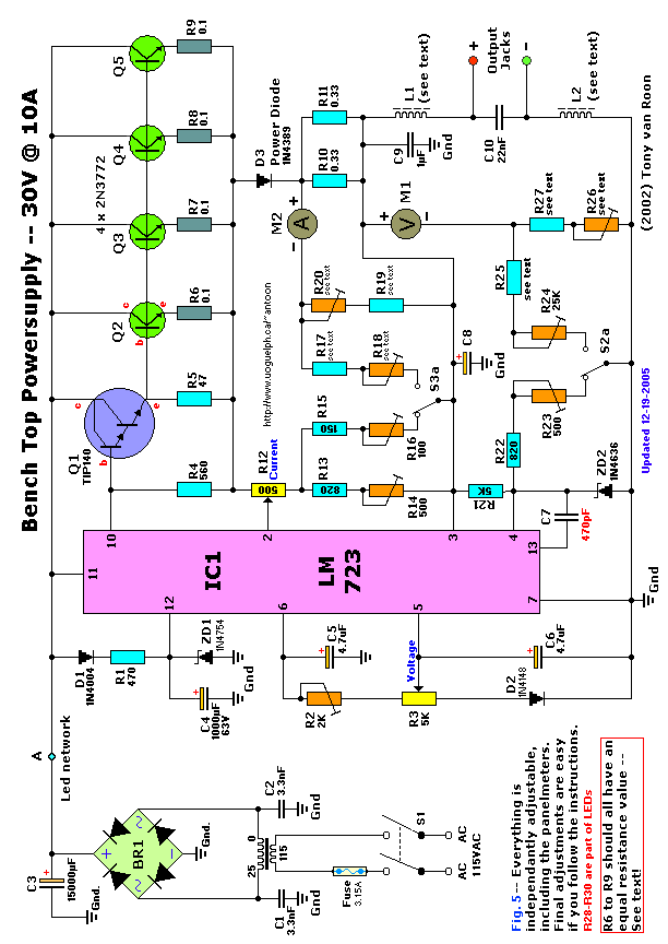
Bench Top Power Supply -- Part 1.
"This 30 volt Bench Top Power Supply is rated at 10 amp, and it is so
versatile and powerful that it will slowly turn your regular 115VAC power drill.
It was designed to work under the most extreme circumstances and fully
short-circuit protected, even in the 10-Amp setting. The optional Cooling fan(s)
keep the semiconductors and the large cooling rib cool
automatically."
by Tony van Roon, VA3AVR
Introduction:
This
"jumbo" power supply is build around the monolithic volt regulator IC from
Motorola, the MC1723, which is the cmos version of the old µA723 from Fairchild
Semiconductors. Other versions of this IC, like the LM723 from National and
others, and even the old MC723 metal-can will work too. The µA723 voltage
regulator was designed by Bob Widlar and 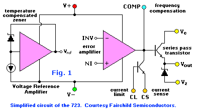 first introduced in 1967, and used ever since. It is a flexible,
easy-to-use regulator with excellent performance. Looking at Fig. 1., this 14 pin regulator is not of your average type.
You find this regulator everywhere, in a variety of applications including
military. This IC can function both as a positive or negative
voltage regulator and designed to deliver a load-current of 150mA DC. With
external 'pass' transistors the output current can be increased to significant
levels, as in our project to about 10 amps (depending on your transformer). A
special temperature monitoring circuit (optional) will activate two to four CPU
fans (optional) automatically if the temperature of the large cool rib exceeds
an adjustable temperature and activate or deactivate the fans within a 2.3°C
temperature variation. Pretty good for a 'cool' rib in my opinion. Even
at 1 amp the cool rib may get warm, but at 10-amp it gets really hot and so the
fans will not only keep the temperature at a safe level it also is an added
safety feature to give this powersupply a life-span of at least 30 years! The
semiconductors in the shaded, light yellow area on the Circuits Diagram
below go all on the large cool rib. See Fig. 5.
first introduced in 1967, and used ever since. It is a flexible,
easy-to-use regulator with excellent performance. Looking at Fig. 1., this 14 pin regulator is not of your average type.
You find this regulator everywhere, in a variety of applications including
military. This IC can function both as a positive or negative
voltage regulator and designed to deliver a load-current of 150mA DC. With
external 'pass' transistors the output current can be increased to significant
levels, as in our project to about 10 amps (depending on your transformer). A
special temperature monitoring circuit (optional) will activate two to four CPU
fans (optional) automatically if the temperature of the large cool rib exceeds
an adjustable temperature and activate or deactivate the fans within a 2.3°C
temperature variation. Pretty good for a 'cool' rib in my opinion. Even
at 1 amp the cool rib may get warm, but at 10-amp it gets really hot and so the
fans will not only keep the temperature at a safe level it also is an added
safety feature to give this powersupply a life-span of at least 30 years! The
semiconductors in the shaded, light yellow area on the Circuits Diagram
below go all on the large cool rib. See Fig. 5.
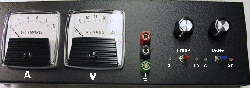
Voltage Output in 'Low'
setting is variable from 0.7 - 6 volts (more later why the 0.7V), in the 'High'
setting the voltage is variable from 3 - 37 volts. Current is adjustable in the
'Low' position from 0 - 1 amp and in the 'High' setting from 1 to 10 amps. 0.1%
line and 0.03% load regulation. Ripple is less than 0.001Vpp. Scale tolerance
Low: 0.2%, High: 0.5%. Another welcome feature is the short-circuit protection.
Beautiful chip. The normal commercial temperature range is 0°C to 70°C
(MC1723CD, CL, CG, and CP package). The military version (MC1723G or L) can
handle a temperature range of -55°C to +125°C. That one you can really freeze or
cook!
Voltage
Regulation:
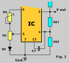
 Shown in Fig. 2. was the initial
idea of voltage regulation and method we will be using. As mentioned before
there are two scales, 0.7 to 6 volts and 3 to 30 volts. A nice problem way to do
that is with a DPDT switch (S2). Plus we will add a Led to indicate which scale
we are on. This toggle-switch switches both the volt-scale and the volt-meter.
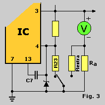
In Fig. 3. you can see how, by putting one side of S2 to
ground via one resistor, the output voltage is in the 3 - 30V scale, and the
other side of S2 via another resistor (R-extra) to switch to the 0.7 - 6 V
scale. At the same time we switch a parallel resistor with it as a shunt for the
panel-meter. If we calculate the value of this resistor to represent the meter
Ri for the 6V scale, then everything is a piece-of-cake. A single
pole switch is in this scenario sufficient, without limiting any performance. A
second pole is used to switch the led-indicators, making S2 a
double-pole-double-throw type. 'Voltage' on the front panel is controlled with
potentiometer R3 and the scale adjusted with trimmer pot R2.
Shown in Fig. 2. was the initial
idea of voltage regulation and method we will be using. As mentioned before
there are two scales, 0.7 to 6 volts and 3 to 30 volts. A nice problem way to do
that is with a DPDT switch (S2). Plus we will add a Led to indicate which scale
we are on. This toggle-switch switches both the volt-scale and the volt-meter.
In Fig. 3. you can see how, by putting one side of S2 to
ground via one resistor, the output voltage is in the 3 - 30V scale, and the
other side of S2 via another resistor (R-extra) to switch to the 0.7 - 6 V
scale. At the same time we switch a parallel resistor with it as a shunt for the
panel-meter. If we calculate the value of this resistor to represent the meter
Ri for the 6V scale, then everything is a piece-of-cake. A single
pole switch is in this scenario sufficient, without limiting any performance. A
second pole is used to switch the led-indicators, making S2 a
double-pole-double-throw type. 'Voltage' on the front panel is controlled with
potentiometer R3 and the scale adjusted with trimmer pot R2.
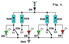 The Led indicators have a voltage of between 1.8 and 2.0
volts dc and the current no more then 25mA max. They can also use be used to
glow on AC, only then an extra diode will be required (see Fig. 4.) which also
protects the Led's just in case we accidentally connect them the wrong way.
Point 'A' is connected to the same as indicated on the circuit diagram. Leds D6
& D8 are for the 30-volt and 10-amp respectively and D5 & D6 are the
6-volt and 1-amp settings but are not lit because they are shorted by the switch
S2b and S3b. Resistors R28 to R31 are chosen accordingly to input voltage. A
rule of thumb is about 100 ohms per volt input voltage. This means a little less
than 10 milliamps per Led and that is enough to light them up. Depending on the
Led type you use (regular, high-, or ultra brightness) you may have to adjust
these resistors to suit your needs. You could use trimmer pots instead of
resistors but that is such an overkill and waste. So, not needed, just a bit of
tinkering may be required. The method of short circuiting the unused leds was
chosen since this was the simplest and cheapest way of going about it. They also
serve as a "On/Off" indicator of the power supply when it is switched on because
a minimum of two led's will always be on. It is okay to use two bi-color leds
but they are more expensive.
The Led indicators have a voltage of between 1.8 and 2.0
volts dc and the current no more then 25mA max. They can also use be used to
glow on AC, only then an extra diode will be required (see Fig. 4.) which also
protects the Led's just in case we accidentally connect them the wrong way.
Point 'A' is connected to the same as indicated on the circuit diagram. Leds D6
& D8 are for the 30-volt and 10-amp respectively and D5 & D6 are the
6-volt and 1-amp settings but are not lit because they are shorted by the switch
S2b and S3b. Resistors R28 to R31 are chosen accordingly to input voltage. A
rule of thumb is about 100 ohms per volt input voltage. This means a little less
than 10 milliamps per Led and that is enough to light them up. Depending on the
Led type you use (regular, high-, or ultra brightness) you may have to adjust
these resistors to suit your needs. You could use trimmer pots instead of
resistors but that is such an overkill and waste. So, not needed, just a bit of
tinkering may be required. The method of short circuiting the unused leds was
chosen since this was the simplest and cheapest way of going about it. They also
serve as a "On/Off" indicator of the power supply when it is switched on because
a minimum of two led's will always be on. It is okay to use two bi-color leds
but they are more expensive.
Part 2 - of
this project will start with the construction of the large cool rib, mounting
and wiring up all semiconductors, and (optionally) the cooling fans. Then the
back panel and the 115VAC wiring of the on/off switch, transformer, fuse holder
and powercord/receptacle, and last the bridge rectifier BR1 and the large
electrolytic capacitor C3. There are lots of photographs and pictures to help
you get through all this. The Printed Circuit Board and Lay-out are also
available in Part 2. The finished product is a worth while project and
outperforms many commercial units.
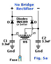
If you have a different transformer with a
CT (Center Tap) or something, like 18-0-18 or 24-0-24, then hook it up as show
in Fig. 5a. This way the transformer will handle the load evenly over both
windings. In this example a bridge rectifier is not required. The rectified
voltage to the circuit needs to stay below 36 Vdc, because that's the max for
the LM723. So, 18 x 1.44pp = 25.92 volts and 24 x 1.44pp = 34.56 volts
DC.
Your transformer should not exceed 25 VAC.
Choose Power Diodes for the
two diodes, 1N4389 similar or better would be a good choice. You can select a
alternate type diode ofcourse if your power supply output current is 5A or less.
In price, however, you probably save only a couple bucks when you choose diodes
with a lower amperage.
Back to Circuits Page or
Continue to Part
2
Copyright © 2002, Tony van Roon,
VA3AVR
Last Updated: January 6,
2006