DO NOT TRY TO DO THIS MOD !!! IF YOU ARE NOT AWARE OF THE SHOCK RISK !!!
I got two old PC powersupplies for free, to be used for this test..
They
are named DTK Computer model PTP-2008. 200 Watt Output.
Original
outputs are:
+5V 20A
+12V 8A
-5V 300mA
-12V 300mA
After modification:
+13.5V 14Amp cont. 20 A for 20 sec.
The
external 230 Volt AC power ON/OFF switch is removed and bypassed.
Old unused
outputs are removed. Over voltage protection changed to only protect one output
at 16 V,
Voltage regulating resistor net changed to only monitor a single
output,
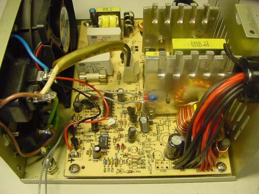
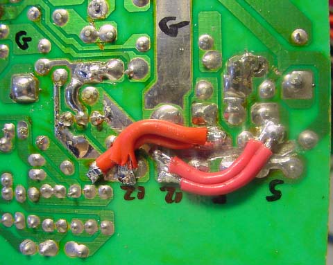
Do it like this:
Cut: white, orange, blue, and yellow wires as close as
possible to the pcb.
Cut: all plugs away in the other end of the black and
red wires, parallel all red and black wires..
Desolder: Fan wires, L1, L3,
L4, R25, R26, R27, R29, R50, R51, R52, R61, R66, D10, D16, D17, C29, C28,
ZD1
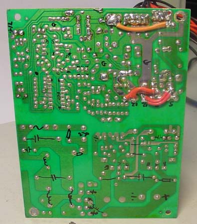
Mount a 680 Ohm 1/4 Watt at R50 location.
Mount solderpins in the
holes for R26, R61 and Fan connection.
This is
a fast part-drawn schematic that only covers what I wanted to know.
Mount
13.5 K Ohm at the solderpins at R26. (13.5 Volt output adjust point)
Mount
15 V Zener and 100 Ohm in series in the ZD1 holes. (Over voltage
protection)
If two or more powersupplies needs to be paralled, then cut
R30,
now it is possible to enter constant current mode opperation without
shutting down.
This is also needed if your load (or radio) has big capasitors
in parallel with the power supply line.
Orange
wire connects unused cap to the new 13.5 Volt output (old +5 Output).
Transformer low
voltage outputs are cutted,
and 12 volt output vindings are connected to the
high current double diode.
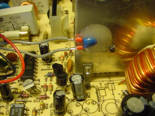
The fan
is reverse mounted so that it will blow cold air into the heatsinks and
transformer.
The NTC is glued with epoxy to the heatsink with the
powerdiode,
The fan controller is changed so that the fan starts to rotate at
+40 C on the heatsink,
If the temperature goes further up, the fan will
rotate faster.
Mount
potentiometer 47 K at R61 solderpoints. (adjust to fan start at 40 C then change
to normal resistor)
Output ripple is under 5mV pp at 20 Amp. (0 - 100 Mhz)
I have tested it
with my HF VHF and UHF rig, and could not hear any more noise than
usual.
Output power has been tested with 14 Amps cont. for one hour, no
problem at all !!
Efficiency at full max load is 60 %
This mod done April 2002 by me OZ2CPU.
Dont ask for schematics or any more
info. All I have is here on this page..
Idea to this mod was found here:
http://www.qrp4u.de/index_en.html
If you want to know more about switchmode converters get the "bible"
called:
Switchmode power supply handbook by Keith Billings. From McGraw-Hill
Company ISBN: 0-07-006719-8
![]()