hey, buddies, this is the time for making a variable power supply for your usage. The main friend of hobbyist electronics is an adjustable power supply circuit. every DIY makers need this kind of bench power supply for making another project. so in this article, we are going to introduce a super friend for your electronic project – DIY 30v 10A DC Variable power supply project.
Variable Power Supply Circuit Diagram
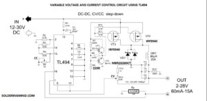
The variable voltage and current control circuit are working based on the switching ic of TL494. The TL494 having two error amplifiers as comparing with SG3525 which will allow you to control the DC voltage and current also.
The connected 10k and 2.2nf will determine the frequency of the output signal. The output signal is about 42Khz. The signal will on/off the MOSFET. The main feature of this adjustable power supply is when a voltage changes in the input will not affect the output stage. so the testing device won’t be damaged.
- Toroidal Transformer Winding Using Formula
- Pir Motion Sensor Home Security Circuit
- Low pass subwoofer filter circuit diagram
- How to Connect Led directly on Ac current
- Simple continuity Tester circuit diagram
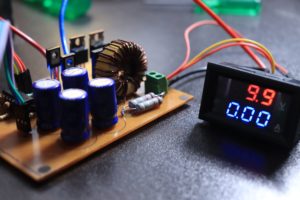
80uH Inductor
I just take the inductor from old induction cooktop. with outer diameter is about 3cm the initial inductance is about 200uH. so I removed a number of coil windings and keeps 30 turns on it. Then it reached near to 82uH. It’s pretty good for this project.
hi thanks for sharing all these circuits i have a question to ask, is it possible to use IRF540 instead of IRF9540??
IRF540 IS N CHANNEL MOSFET AND IRF 9540 IS P CHANNEL MOSFET
the mosfets are drawn as n channel
NO IT IS A P CHANNEL MOSFET
For IRF9540, the gate-source limit value is 20 Volts, and in the circuit, with a source voltage of 30 Volts, this voltage will be exceeded.
NO PROBLEM IF YOU FEED 30V THE OUTPUT WILL BE 20V
a – no, there is a divisor by 2
why are R7 and R9 different in power?
why don’t I see my comments?
Please tell me how to can I use n Channel MOSFET and don’t have p channel MOSFET
If I calculate the used values for current and voltage limit, the voltage limit is about 15.6V and the current limit is about 25.6A. Can you tell me how you calculated the voltage dividers?