
 The voltage control in the
voltage variable type 3 terminal regulator The voltage control in the
voltage variable type 3 terminal regulator
In
case of the 3 terminal regulator that is using this time, the output
voltage can be changed by changing the value of the
resistor.
LM317 is for the positive power supply
and LM337 is for the negative power supply. Either of the operation works
similarly.
 The voltage control
range The voltage control
range
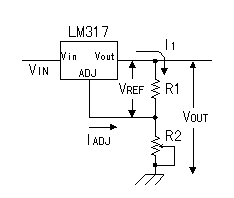 The figure on the left is the basic
circuit of the regulator. The nominal reference voltage between Vo and Adj
is 1.25 V, being constant. The figure on the left is the basic
circuit of the regulator. The nominal reference voltage between Vo and Adj
is 1.25 V, being constant.
It is possible to do the
adjustment of the output voltage by changing the value of
R2.
The output voltage (Vout) can be calculated by
the following formula.
Vout = 1.25 ( 1 + R2/R1) +
IADJ(R2)
IADJ
is the electric current which flows from the Adj pin and it is tens of µA.
Because it is, you can omit it, too.
There is
limitation to decide the resistance value for the voltage adjustment in
LM3xx. It is the limitation that the
voltage control doesn't work normally when the output current is not equal
to or more than 10 mA. You do not need to consider
this limitation when the load which the equal to or more than 10 mA
electric current always flows through is connected. However, when there is
a condition of the no-load like the power supply for the experiment and so
on, you must consider this limitation. That you consider is the fact to
make the value of R1 about 120
ohm. In this way, the output current flows by 10 mA
even if it is minimum.
The value of R2 can be
calculated by the following formula.(It ignores
IADJ).
R2 = 120 ( Vout/1.25 - 1
)
In case of the 5 V output voltage, it
is as follows.
| R2 |
= 120 x ( 5/1.25 - 1 ) |
|
= 120 x 3 |
|
= 360 ohm |
I used the 500 ohm variable resistor with the circuit this time.
Because it is, the adjustment range with the output voltage becomes 1.25V
to 6.46V in the calculation.
The condition with the input
voltage
In case of LM3xx, doing 3 V of
minimum the differences between the input voltage and the output voltage
are necessary. That is, the input
voltage must be equal to or more than 3 V higher than the output
voltage. In case of the 5 V output voltage, equal to
or more than 8 V of the input voltage are necessary.
In case of LM317, the difference with voltage of the input and the
output is a maximum of 40 V. Because the most low voltage of the output is
1.25 V, the upper limit with the input voltage becomes 41.25 V correctly.
Generally, it makes the maximum input voltage 40 V. Because it is,
the voltage adjustment range by LM317
becomes 1.25V - 37V.
In LM337,
the polarity with the voltage is opposite but the adjustment range is
same.
The protection of the
regulator
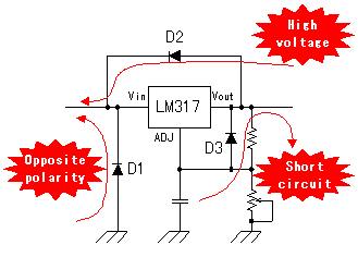 I put some diodes outside the regulator.
They are protecting the regulator. Even if it doesn't put these diodes,
the regulator works. I considered the accident and put these
diodes. I put some diodes outside the regulator.
They are protecting the regulator. Even if it doesn't put these diodes,
the regulator works. I considered the accident and put these
diodes.
D1 is the protection when
the voltage of the opposite polarity is applied to the
input.
When having the rectification circuit of the
AC power supply, the voltage which is opposite is not applied. If you are
careful at the time of the construction, you do not need to put this
diode. Because the equipment which was made this time is the way of
connecting the ±12V power unit outside with the wire, then I put this
diode. I used the diode for 1A. In case of being the power supply outside
without 1A current limiting circuit's, the diode breaks.
The silicon diode becomes the short circuit condition when it
breaks. The power unit may break when the outside power supply doesn't
have the protection network.
D2
is the protection when the output voltage becomes higher than the input
voltage.
When there are a coil and so on in the
load circuit, there is possibility that the high voltage comes out when
blocking off the electric current.
D3 is the protection when the output voltage falls from the voltage
of the voltage adjustment pin.
When the output
short-circuits, it becomes such a case.
|