
Switching power supply
Why to build
switching power supply and why not to stay with conventional linear regulators.
Here are some facts that will bet on switcher:
- Efficency of this switcher is around 85% - and it depends on the
load
- For the same power output its size is up to 5 times smaller
- Element count is small, becouse the regulator chip has everything
integrated
- Current limit
- Adjustable output voltage
- Shutdown when overheated (build
temperature sensor)
- Measure and regulate output voltage
- High frequency switching (200kHz)
- No 50Hz hum
- Becouse of high efficiency, small or none cooling system is needed
Specificaly for the chip that is used in this circuit data
are like this: Oscilator runs at freq 200kHz, output noise is below 1% (worst
case), max current is 4A at 20V. Voltage can be regulated from 0,0 V (true
zero), to 40 V. Voltage and current limit, can be adjusted. You should take
special care when purchasing choke. Its ferrite material should be build for
frequencies up to 300kHz. Input to the regulator can be DC or AC voltage -
becouse the input is rectifier bridge.
Switching power
supply schematics.
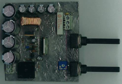
Switching power
supply printed circuit board. And one more trick: Switching power supply
prodeces a lot of EM (electro-magnetic) noise. You should have this in mind when
building supply. One way to reduce the noise is to make the top side of the
board a ground plane, and ofcourse a good choke will do the rest.
And last but not least - high resolution postscript files needed to
build the device
- Schematics . . . PS, PDF
- Printed circuit board . . . PS, PDF
- Position of elements . . . PS, PDF