20 Amp Variable Power Supply using LM317
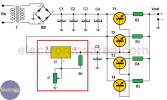
This 20 Amp Variable Power Supply varies its output voltage from 1.5 to 15 volts and is based on the well-known variable voltage source configuration, where only the LM317 voltage regulator is used. See red box on the diagram.
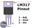
The output voltage of this basic regulator is adjusted with the potentiometer connected to the regulator pin 3 (adj). On this power voltage source, the level of the output voltage is regulated in the same way.
The basic regulator has a maximum current capacity of 1.5 amps. (acceptable for most cases). To amplify the current capacity of this regulator we place four power NPN power transistors as shown on the diagram.

How the 20 Amp Variable Power Supply works?
The output of the LM317 voltage regulator (pin 2) is connected to the 4 power transistors bases. These transistor are conected in parallel. The output voltage of the 20 Amp Variable Power Supply is obtained from the junction of the 4 resistors (R2, R3, R4, R5), connected to the emitters of the 4 transitors.

The emitter voltage of each transistor is: Ve = Vb – 0.7 V (approximately), where:
Resistors in series with each emitter are placed in order to compensate for voltage differences that may exist among the 4 emitter voltages.

List of circuit components for the 20 Amp Variable Power Supply
This 20 Amp Variable Power Supply varies its output voltage from 1.5 to 15 volts and is based on the well-known variable voltage source configuration, where only the LM317 voltage regulator is used. See red box on the diagram.
The output voltage of this basic regulator is adjusted with the potentiometer connected to the regulator pin 3 (adj). On this power voltage source, the level of the output voltage is regulated in the same way.
The basic regulator has a maximum current capacity of 1.5 amps. (acceptable for most cases). To amplify the current capacity of this regulator we place four power NPN power transistors as shown on the diagram.
How the 20 Amp Variable Power Supply works?
The output of the LM317 voltage regulator (pin 2) is connected to the 4 power transistors bases. These transistor are conected in parallel. The output voltage of the 20 Amp Variable Power Supply is obtained from the junction of the 4 resistors (R2, R3, R4, R5), connected to the emitters of the 4 transitors.
The emitter voltage of each transistor is: Ve = Vb – 0.7 V (approximately), where:
- Ve = Emitter voltage
- Vb = Base voltage
Resistors in series with each emitter are placed in order to compensate for voltage differences that may exist among the 4 emitter voltages.
List of circuit components for the 20 Amp Variable Power Supply
- 1 110/220 VAC to 18 VAC transformer, 15 Amp. (T)
- 1 30 amp. / 300 volts diode bridge. (DB)
- 4 4200 uF / 40V electrolytic capacitors (C1, C2, C3. C4).
- 1 10 uF / 40V electrolytic capacitor (C5)
- 1 LM317 voltage regulator. (U)
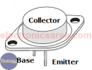
- 4 2N3055 NPN transistors (T1, T2, T3, T4)
- 1 270 ohms, 1/2 watt resistor (R1)
- 4 0.47 ohms / 10 wats resistors (R2, R3, R4, R5).
- 1 100k potentiometer (P)
- 4 heatsinks (1 heatsink for each transistor) or a large heatsink for all transistors